Pcomp Midterm
 - October 25, 2017
The midterm project. Two weeks and a chance to use what we have learned in class so far. We were put in groups of two and the assignment was to come up with an interactive product to show in class.
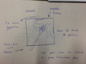
My partner and I had several ideas about what to do, so we sat down and agreed on a couple of them. We came up with the idea of using proximity sensors to control a pen on a canvas. After speaking to Tom we adjusted our idea and quickly decided instead to use similar sensors to control a p5 sketch. We were both fascinated by the idea of using an intangible control – to me, the idea of handgestures is very compelling and I think we are going to see more of it when we advance from touch screens (a good read on that is Bret Victor: A brief Rant on the future of interaction design. Also in relation to that I find “Project Soli” by Google ATAP very interesting). As we were tuned in on an idea the first step was choosing the right sensor to detect our movement. Some of the options were IR-sensors and Ultrasonic sensors. Another option was to use a “Leap Motion”. My experience with the leap motion is good. However, I also felt like using that type of sensor for this project would be a potential shortcut and that I wouldn’t learn as much from it. Instead we decided to go with the ultrasonic sensor. From what I have heard, these have a longer range that the other distance sensors, which potentially could be useful for the project. We were aware that this type of sensor is cheap and generally in bad standing among people who has been using them. Making this sensor work ‘well’ was one of the challenges in this project that I really liked. We used sensors of the brand SainSmart HC-SR04. We wanted to have two. One controlling the x-axis and one controlling the y-axis. As shown in this early sketch we considered attaching them on a frame (vertical position) so that people would put their arm into the frame – using the frame as an indicator of where you could position your arm.
Step 1: Getting one sensor to work The first thing we needed to do, was to get a sensor to work. We used a basic tutorial by Dejan Nedelkovski on the “How to mechatronics” webpage to arrange the trigger and echo sensors. This was pretty simple. We quickly realized that the sensor measurements we got from the sensor was all over the place – a small misplacement of the hand and we would get ranges that were far out of the range. For the correction of this we used a serial connection to a computer and drew an ellipse – we then used the ellipse to visualize the numbers we got from the sensor. We used p5 to write a code where we would only use the numbers within a certain range. When using the Arduino serial monitor we found that the ranges between 2cm and 50cm were very consistant – based on that we wrote a p5 sketch that would only us the numbers within that range. These numbers were pushed into a array and the average of all the numbers were calculated and used as either the xValue or yValue. The xValue and yValue was then mapped to the canvasWidth and Height, respectively. Some of the necessary adjustments during this phase was to figure out how far of a reach (physically) you wanted to the sensor to have – but also determining the length of your array for xPos and yPos. If the length of the array is long you are going to have a precise but slow response, whereas a small array will be more responsive but more vulnerable to small changes in the measures. This video shows what our initial measurements (before a proper correction) looked like:
Step 2: Getting two sensors to work Setting up two sensors was not too complicated either. One thing to be aware of, that caused some trouble was that you can’t have two “pulseIn/EchoReads” simultaneously therefore the code needed to be rearranged to give two readings. Another thing that was added at this point was a Serial handshake. There was a lot of incoming data to the p5 sketch. The buffer filled up quickly and even the smallest error in the sketch would crash the browser – this was quickly fixed with a Serial-handshake. Now that we had two functioning sensors mapping the next step was to test the position of the sensors. What way to turn them? Where to place the xSensor and where to place the ySensor. At first the sensors were placed on a table facing the same area (like a coordinate system). When placing your hand on the table (as in the previous video) there would be a big hand-surface-area for the xSensor to detect whereas the ySensor would be reading the location based on the small area created by the top of your hand. For this setup to work it was necessary to hold something in your hand – like a cube or a glass. The following video shows how it worked. At this point we had also added a on/off switch and a light to indicate the on/off state.
When testing different setups with the sensors we realized that the accuracy and general control was better when the sensors were pointing in different directions. Therefore we decided to change the control into something where you needed two hands for control instead of just one. The following is showing some of the different setups:
For this setup the sensors are placed on the wall behind the computer. One is facing in a up/down direction (right of the computer). The other is positioned in a right/left direction (left of the computer). Also, on the table there are marks from the ‘range’ testing.
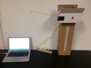
For this setup a cardboard prototype was created. The ySensor is pointing down and the xSensor is coming out of the left side of the box. Tape is used as an indicator for where to put your hands. It also labels the length of sensors reach.
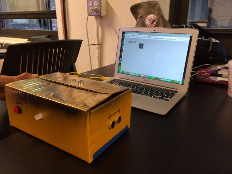
Step 3. Final decisions After some testing (and many discussions) we created a final case and setup. It was determined that the box would be in front of you. The ySensor would be placed on top of the box, whereas the xSensor would be placed on the side. We decided to go with a simple cardboard case (to limit waste of resources). Lights, wires and the on/off button was attached to the box, giving us the following product. We also moved our sketch from the p5 online browser to a local browser. This had a dramatic effect on the speed and control of the sketch.
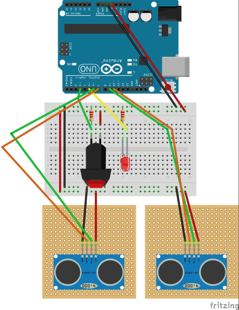
The sensors were soldered to pinboards to make them fit inside the box. The following shows the wiring of the Arduino.
A simple game was created. Our thoughts were to create a game where you would need accuracy and therefore precision and concentration on your arm gestures. Ideally, we wanted to create a maze, that you had to get through on time. However, we realized that collision between two objects is difficult when using Serial input from sensors like these. Instead we created a simple sketch similar to snake, where you had to move the curser into a certain area on the screen.