Designing for Digital fabrication - Project Proposal
 - October 04, 2018
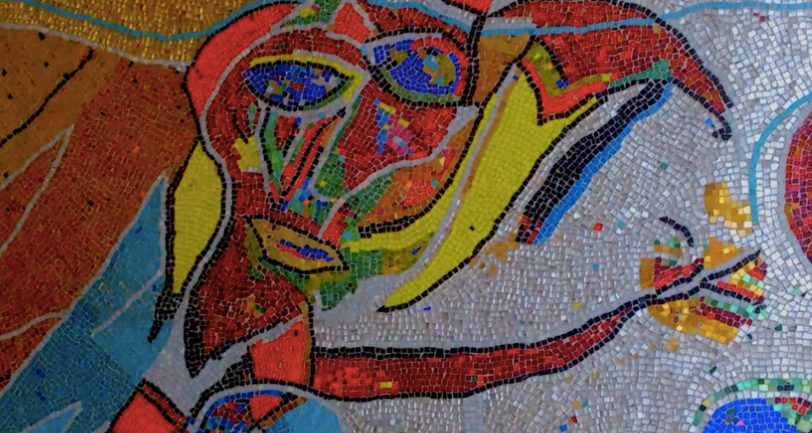
For this project I would like to convert a painting into a mosaic piece. Using a “tile” sketch and a “color/contour” sketch made in processing my idea is to import it into Vectorworks and laser-etch tile instructions to a surface - to which I will add glass mosaic.
This project is inspired by Carl Henning Pedersen, a danish modern artist, who did a lot of mosaic pieces in Denmark in the 80’s.
My idea is to take an already existing painting and turn it into a grid/tiles using processing. Each tile in the grid will use a letter for the color. Ex. r = red, g = green, b=blue, since colors don’t get transferred into vectorWorks, the letter will indicate the color of the specific tile.
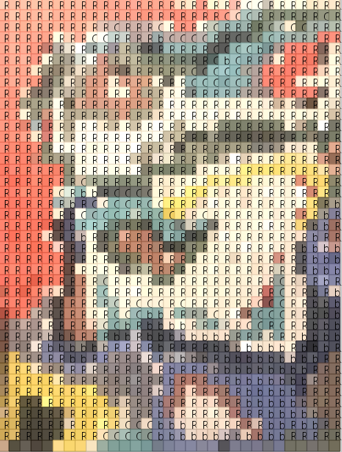
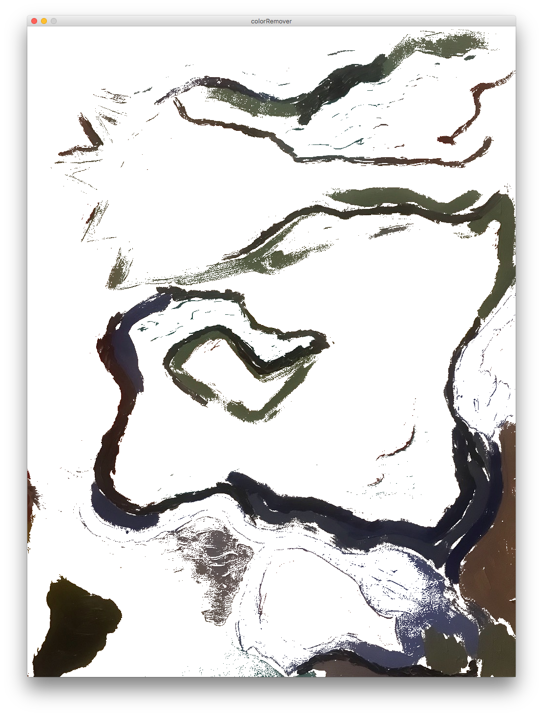
Printing this into a surface would indicate where to place the tiles and also which color to use. To avoid a monotonous expression of all tiles being placed in the similar grid-like structure, my idea was to select certain colors from an image, red, blue or green and get the contour of the color. It could look something like the following.
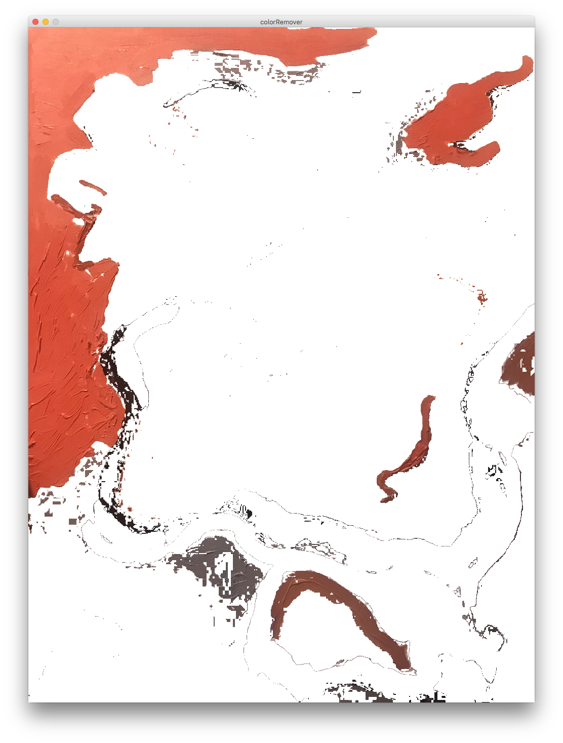
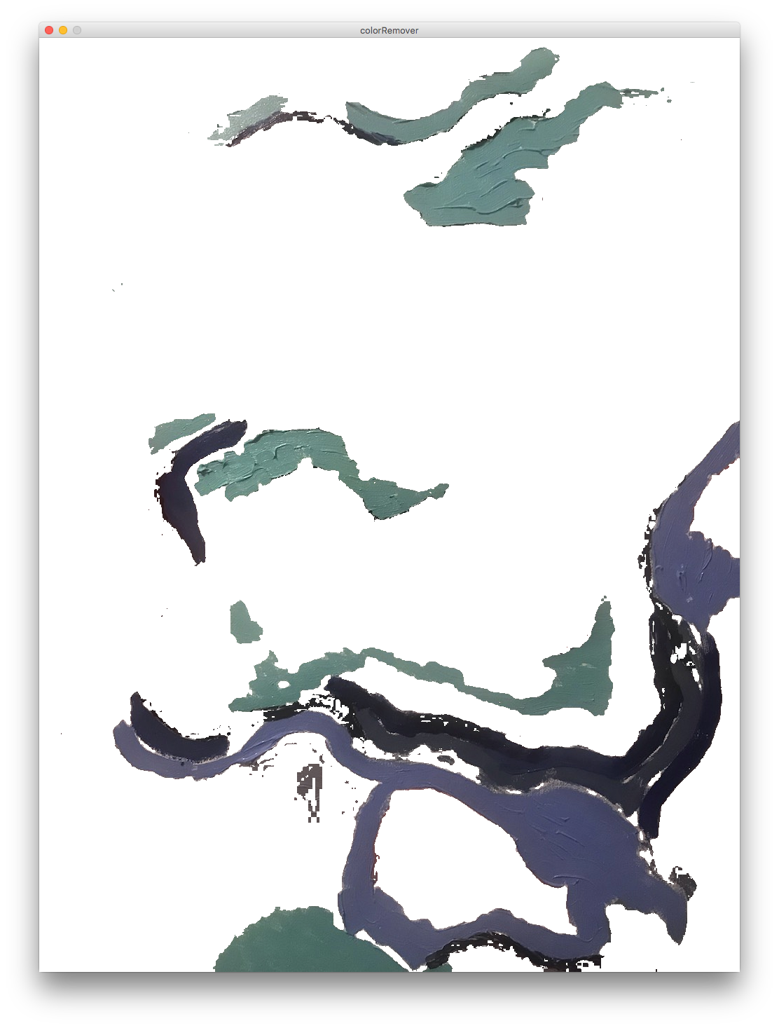
In the first image red has been selected and isolated - in the other it is green/blue.
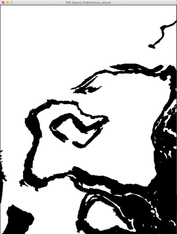
When the colors are selected they can be run through the contour processing sketch that we were provided in-class last week. Here is an example of the “dark” colors before and after going through the contour algorithm.
Before:
After:
The contour image can then be imported into VectorWorks and cleaned up. The following image is showing some of the steps.
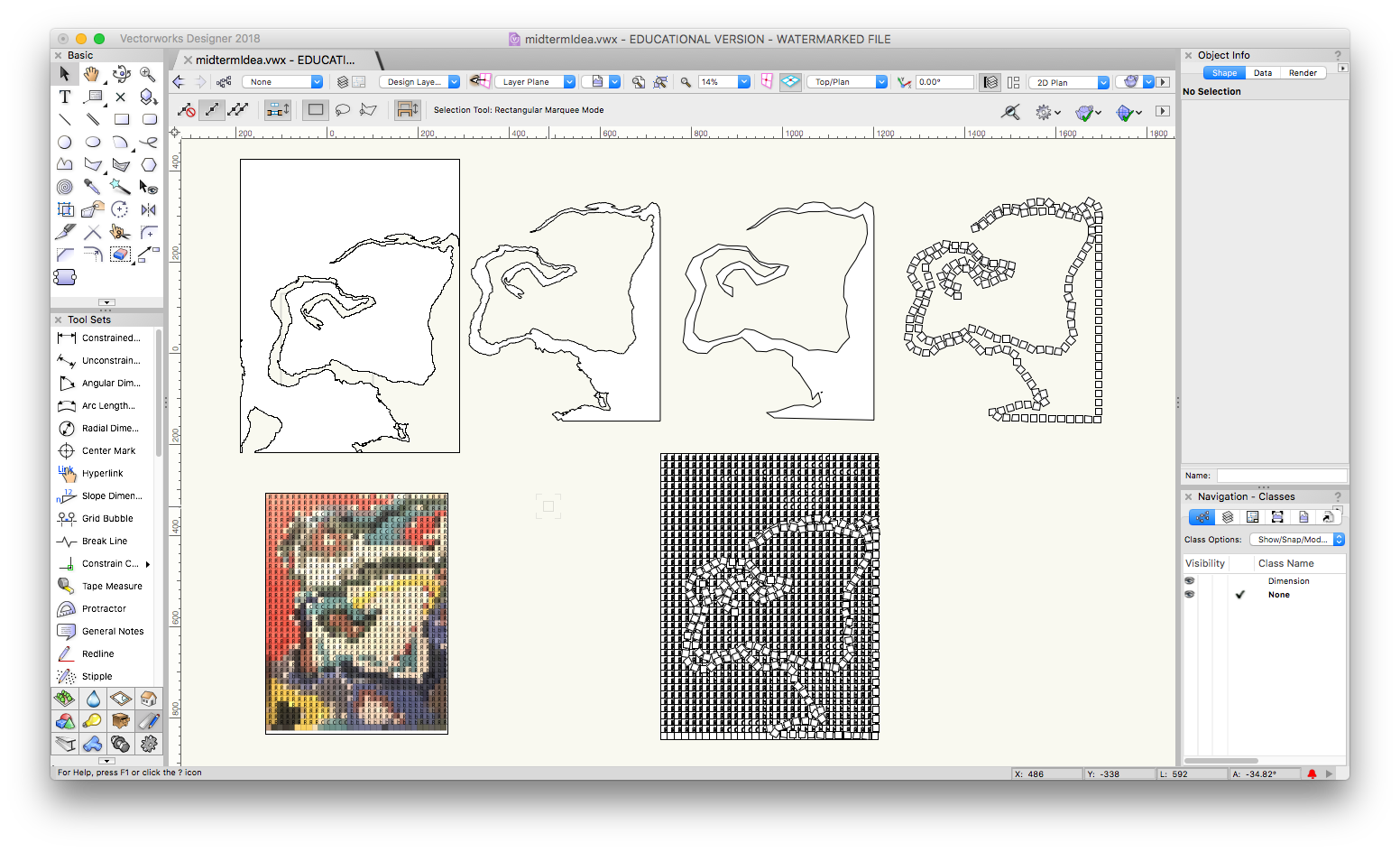
- the polygon is created using the inner boundary mode attribute in the tools.
- the shape is simplified (using modify -> drafting aids -> simplify polys)
- tiles are added to the path (duplicate along path)
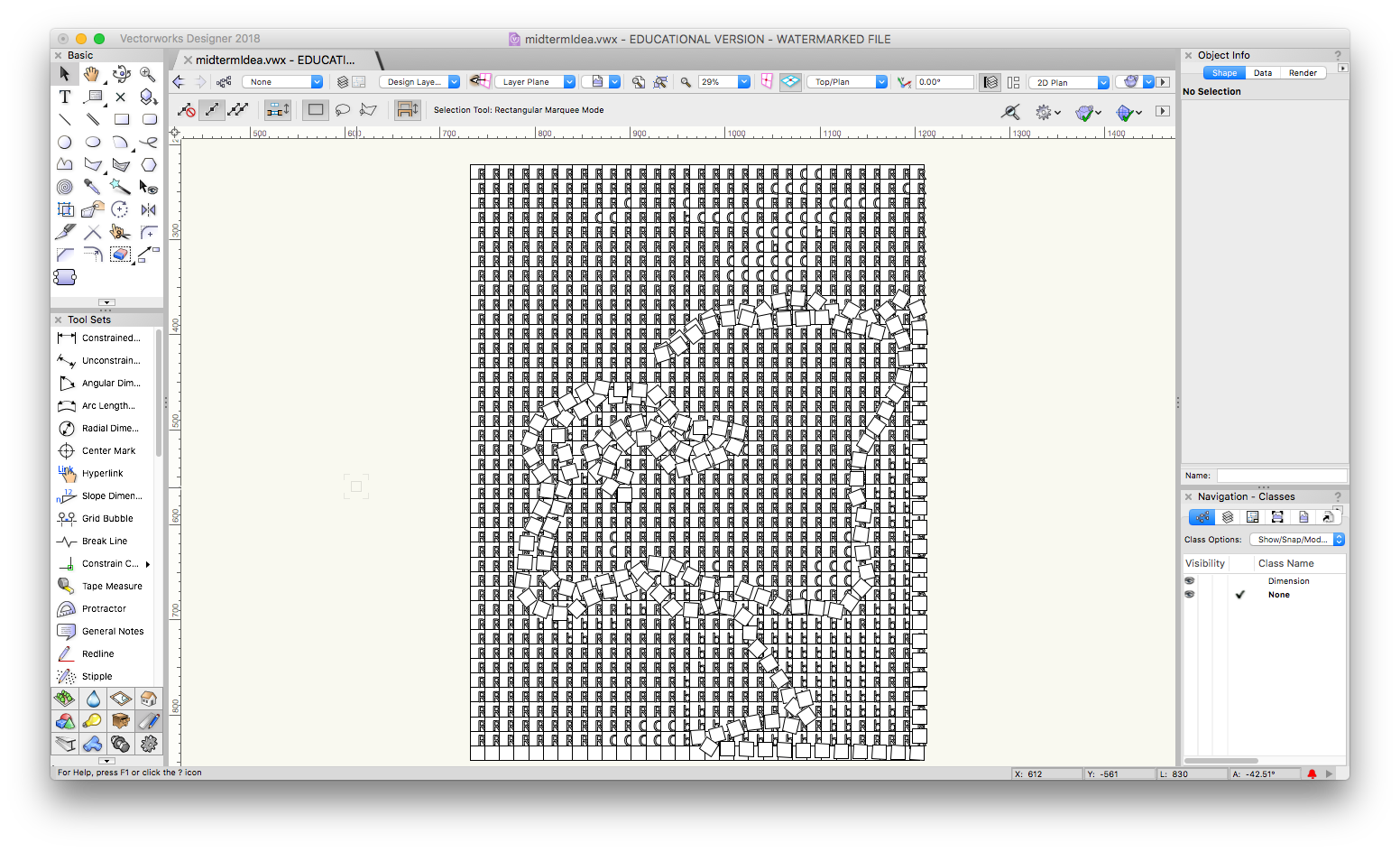
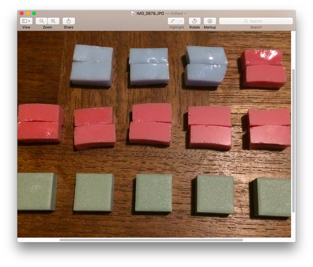
Using this method I am planning to chose certain colors and have them “break” the grid-system. Then, hopefully, for the manual work, all I have to do is follow these instructions etched into the surface telling me what angle to place the tiles in and what color to use. Here’s a few examples of the glass/ceramic tiles I’m considering for the image:
The process is almost like a digital litograph. Selecting a color individually, getting the contour of its shape and then adding its “instructions” to the image.